- 您现在的位置:买卖IC网 > Sheet目录17360 > AS1339 EB (ams)BOARD EVAL AS1339
�� �
�
�AS1339�
�Datasheet� -� A� p� p� l� i� c� a� t� i� o� n� I� n� f� o� r� m� a� t� i� o� n�
�Capacitor� Selection� for� LDO’s�
�Input� Capacitor�
�The� capacitor� for� the� LDO� Input� should� have� at� least� a� value� of� the� sum� of� the� output� capacitors� of� LDO1� and� LDO2.�
�With� a� larger� input� capacitance� and� lower� ESR� a� better� noise� rejection� and� line� transient� response� can� be� achieved.�
�Output� Capacitor�
�For� the� LDO� outputs� the� capacitor� value� depends� on� the� needed� load� current.� For� a� stable� operation� with� rated� maxi-�
�mum� load� currents� a� minimum� output� capacitor� of� 1μF� is� recommended.� At� light� loads� of� 10mA� or� less� a� 0.1μF� capac-�
�itor� is� sufficient.� With� larger� output� capacitance� a� reduced� output� noise,� improved� load-transient� response,� better�
�stability� and� power-supply� rejection� can� be� achieved.�
�Table� 7.� Recommended� Capacitors� for� the� LDO’s�
�Name�
�C� IN2� ,� C� LDO1� ,�
�C� LDO2�
�Part� Number�
�C0402C104K4RAC�
�GRM155R61A105KE15�
�C�
�100nF�
�1μF�
�Voltage�
�16V�
�10V�
�Type�
�X7R�
�X5R�
�Size�
�0402�
�0402�
�Manufacturer�
�KEMET�
��Murata�
��Inductor� Selection�
�For� most� applications� the� value� of� the� external� inductor� should� be� in� the� range� of� 1.5μH� to� 4.7μH� as� the� inductor� value�
�has� a� direct� effect� on� the� ripple� current.� The� selected� inductor� must� be� rated� for� its� DC� resistance� and� saturation� cur-�
�rent.� The� inductor� ripple� current� (� Δ� I� L� )� decreases� with� higher� inductance� and� increases� with� higher� V� IN� to� V� OUT� .�
�In� Equation� (EQ� 3)� the� maximum� inductor� current� in� PWM� mode� under� static� load� conditions� is� calculated.� The� satura-�
�tion� current� of� the� inductor� should� be� rated� higher� than� the� maximum� inductor� current� as� calculated� with� Equation� (EQ�
�4)� .� This� is� recommended� because� the� inductor� current� will� rise� above� the� calculated� value� during� heavy� load� tran-�
�sients.�
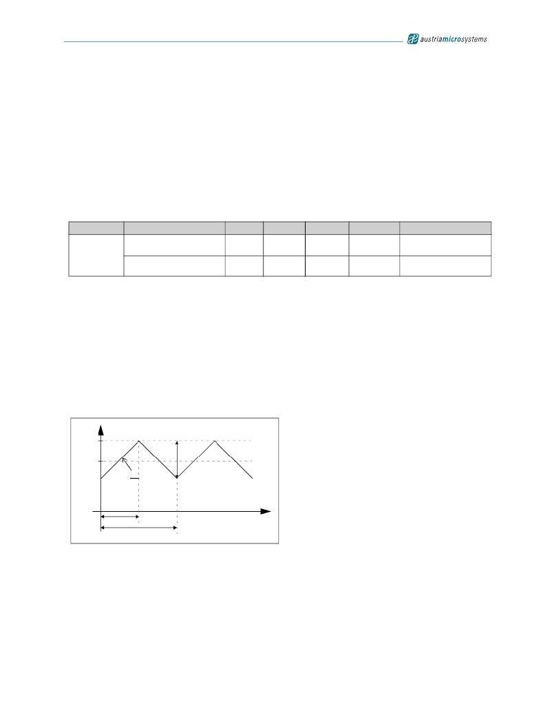
�The� inductor� current� ripple� Δ� I� L� (see� EQ� 3)� is� defined� by� the� slope� of� the� current� (dI� /� dt)� (see� EQ� 1)� multiplied� by� the�
��Figure� 51.� Ripple� Current� Diagram�
�I� L�
�I� Lmax�
�I� OUTmax�
�t� ON�
�dI�
�dt�
�1/f�
�Δ� I� L�
�t�
�dI� -�
�V� IN� –� V� OUT�
�----� =� ----------------------------�
�dt� L�
�(EQ� 1)�
�t� ON� =� DutyCycle� � ---�
�V� OUT�
�1�
�f�
�DutyCycle� =� -------------�
�V� IN�
�(EQ� 2)�
��Revision� 1.05�
�19� -� 25�
�发布紧急采购,3分钟左右您将得到回复。
相关PDF资料
RB-1512S/H
CONV DC/DC 1W 15VIN 12VOUT
MIC2545A-2BM
IC SW CURR LIMIT HI SIDE 8-SOP
F971A336MCC
CAP TANT 33UF 10V 20% 2312
RB-1509S/H
CONV DC/DC 1W 15VIN 09VOUT
SB350-E3/54
DIODE SCHOTTKY 50V 3A AXIAL
MIC2505BN
IC SW SGL 2A HIGH SIDE 8-DIP
MIC2505BM TR
IC SW SGL 2A HIGH SIDE 8-SOIC
TAAB685K035G
CAP TANT 6.8UF 35V 10% AXIAL
相关代理商/技术参数
AS1339-BWLT
功能描述:IC CONV BUCK 650MA 16-WLP RoHS:是 类别:集成电路 (IC) >> PMIC - 稳压器 - 专用型 系列:- 标准包装:43 系列:- 应用:控制器,Intel VR11 输入电压:5 V ~ 12 V 输出数:1 输出电压:0.5 V ~ 1.6 V 工作温度:-40°C ~ 85°C 安装类型:表面贴装 封装/外壳:48-VFQFN 裸露焊盘 供应商设备封装:48-QFN(7x7) 包装:管件
AS1339-DB
制造商:ams 功能描述:Evaluation Board
AS1339-EB
功能描述:电源管理IC开发工具 AS1339 Evaluation Board RoHS:否 制造商:Maxim Integrated 产品:Evaluation Kits 类型:Battery Management 工具用于评估:MAX17710GB 输入电压: 输出电压:1.8 V
AS133R0HLF
制造商:TT Electronics / IRC 功能描述:AS133R0HLF
AS133R0JLF
制造商:TT Electronics / IRC 功能描述:AS133R0JLF
AS133R2FLF
制造商:TT Electronics / IRC 功能描述:AS133R2FLF
AS133R2HLF
制造商:TT Electronics / IRC 功能描述:AS133R2HLF
AS133R2JLF
制造商:TT Electronics / IRC 功能描述:AS133R2JLF